NEC Chapter 9 Tables Explained: Table 1, Table 4, and Table 5 for Conduit Fill
Everything you need to know about the 'Engine Room' of conduit fill — NEC Chapter 9. Learn how Table 1, Table 4, and Table 5 work together to ensure your electrical runs are safe, legal, and easy to pull.

Sander K. Osei
Electrical Engineer (PE)
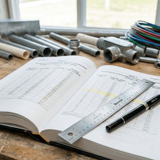
Table of Contents
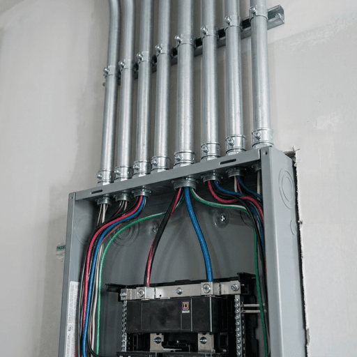
If you’ve ever felt overwhelmed by the National Electrical Code (NEC), you aren’t alone. It’s a massive book with thousands of rules. But for conduit fill, the real action happens in one specific “Engine Room”: Chapter 9.
Chapter 9 is where the dense, theoretical rules of the various raceway articles (like Article 358 for EMT) transform into practical, usable math. Mastering the relationship between Table 1, Table 4, and Table 5 is the difference between an electrician who “guesses” and one who provides a 100% compliant, mathematically defensible installation.
In this guide, we’ll explain how these three tables work together, the “hidden” rules in the Notes, and exactly how to navigate them like a master electrician.
Table 1: The “Golden Rules” of Percentage
The very first table in Chapter 9 is called Table 1: Percent of Cross-Sectional Area of Conduit and Tubing for Conductors and Cables. This table is the foundational source for the percentages we use every day:
- 1 Conductor: 53% Fill allowed
- 2 Conductors: 31% Fill allowed
- 3 or More Conductors: 40% Fill allowed
Why the 31% Penalty for Two Wires?
Newer electricians often ask why the limit for two wires is lower than for three or more. This is because of “jamming.” When two conductors are pulled together, they are more likely to twist over one another and “jam” against the walls of the conduit during a bend. The lower limit (31%) ensures there is extra space for them to slide past each other during the turn.
Table 4: The Dimensions of the Pipe
Once you know your percentage, you need to know how much total air space is inside your conduit. This is where Table 4 comes in.
Table 4 is actually a collection of many tables, one for each type of conduit material:
- Table 4 (EMT): Electrical Metallic Tubing
- Table 4 (PVC Sch 40/80): Polyvinyl Chloride Conduit
- Table 4 (IMC/RMC): Intermediate and Rigid Metal Conduit
For every trade size (1/2”, 3/4”, 1”, etc.), Table 4 lists:
- Total Area (100%): The absolute maximum volume.
- Over 2 Cond. (40%): The pre-calculated space available for the standard 3+ wire scenario.
Table 5: The Dimensions of the Wire
Finally, you need to know how much space your wires will occupy. Table 5 is the exhaustive list of conductor dimensions.
It is organized by:
- Insulation Type: (THHN, XHHW, RHW, etc.)
- AWG/kcmil Size: (Gauge)
For each combination, Table 5 lists:
- Approximate Diameter (inch): The “OD” or Outer Diameter.
- Approximate Area (square inch): The cross-sectional area including the insulation.
Pro Tip: Never use the “nominal” copper area for fill math. You MUST use the values in Table 5 because they include the thickness of the insulation jacket.
The Secret Ingredient: “Notes to Tables”
Just before Table 1 begins, there are several numbered Notes to Tables. These notes are the “fine print” that can make or break your job.
- Note 4 (Nipples): If your conduit run is 24 inches or less, the 40% rule disappears. You are allowed to fill the nipple up to 60% of its area.
- Note 5 (Actual Area): This note requires you to use the actual areas from Table 5, even if they differ slightly between manufacturers.
- Note 9 (Multi-conductor Cables): If you are pulling a single multi-conductor cable (like a tray cable), it counts as a single conductor for the 53% rule, even though it contains multiple wires inside.
How to Conduct a Search in Chapter 9 (Workout Example)
Let’s say you’re pulling six #12 THHN wires into a 1/2-inch EMT conduit.
- Table 5: Look up #12 THHN. The area is 0.0133 sq. in.
- The Math: 6 x 0.0133 = 0.0798 total sq. in.
- Table 4 (EMT): Find 1/2-inch trade size. Look at the Over 2 Cond. (40%) column. The value is 0.122 sq. in.
- The Verdict: 0.0798 is less than 0.122. The installation is 100% code-compliant!

Conclusion: Mastering the Reference Book
Chapter 9 is the ultimate source of truth for conduit fill. By understanding the three-way relationship between Table 1 (Rules), Table 4 (Conduit), and Table 5 (Wires), you transform yourself from an installer into an electrical professional.
Don’t let the tables intimidate you. Once you understand their structure and know the Notes to Tables, you have everything you need to size any raceway with confidence.
Want to stop flipping back and forth? Use our Professional Chapter 9 Calculator Tool for instant data lookups from all three tables simultaneously.
? Frequently Asked Questions
What is NEC Chapter 9, Table 1?
What is NEC Chapter 9, Table 4?
What is NEC Chapter 9, Table 5?
Why is Table 1 different for 2 wires vs 3+ wires?
How do the 'Notes to Tables' affect my calculations?
About Sander K. Osei
Sander is a Professional Engineer (PE) licensed in Texas and Georgia, specializing in power distribution systems and electrical code compliance for commercial construction. With a B.S. in Electrical Engineering from Georgia Tech and 11 years of consulting experience, He reviews technical content on this site for accuracy against the latest NEC edition. Sander ensures every calculator result and code reference reflects what inspectors actually enforce.